002 2021-01-13
Rust embedded driver for Microchip 23x SRAM/NVSRAM
Update January 24, 2021: The driver was successfully tested on Longan Nano, Longan Nano Lite, and Microchip 23K640, 23K256, and 23LCV1024 memory devices.
This post explains the usage of my first embedded Rust driver, the Microchip 23x SRAM driver.
I started learning to program in Rust about 3 months ago, and it's been quite englightening.
I've spent the last five years or so coding almost exclusively in PicoLisp, so it was quite a 180 jumping into a language like Rust. I personally still do prefer PicoLisp as a primary programming language, but for low-level applications it's rather less than ideal.
My use-case
As a member of the RISC-V Foundation, I opted to move my testing to an actual hardware implementation of their open instruction set, the inexpensive Longan Nano, because it also runs Rust.
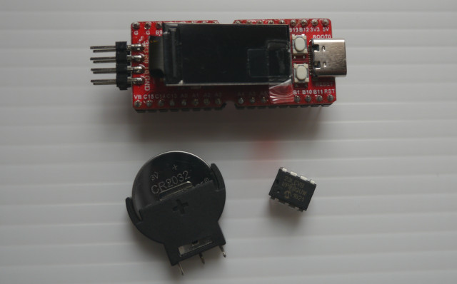
I ran my tests on the (GD32VF103C8T6), which is limited to 20KB of SRAM, as well as the (GD32VF103CBT6) model which has 32KB. For my application I needed a bit more than that, so I set out to wire up an old 1Mbit (128KB) Microchip SPI SRAM chip on my breadboard, only to find out there wasn't a working driver for it.
In fact, the whole SPI on Longan Nano thing is mostly undocumented and completely alien to someone unfamiliar with STM32-like devices. Figuring that out was a learning experience which I'll share with you here.
Now, a few, different, drivers, could be tweaked to talk to the device, but I figured since these chips are available in DIP format, there must surely be other makers holding onto these. That's what led to the creation of this driver.
Hardware wiring
Below I'll discuss how the code was tested with real hardware (Longan Nano + Microchip 23LCV1024). Output will be displayed on the LCD wired to SPI0.
Assuming you've successfully compiled and flashed an example Rust firmware to your Longan Nano, the next step is to wire the SPI RAM to the device.
Hint: If you have the _GD32VF103CBT6 model instead of the GD32VF103C8T6 model, you'll need to edit the .cargo/config file in the longan-nano repo to link with memory-cb.x file instead of memory-c8.x.
Hint: This MCU provides 5 GPIO ports with 16 pins each (total 80). It also contains 3 hardware SPI interfaces, and you're free to physically wire the SRAM pins to the same SPI device as the LCD (SPI0) for example, as long as you use an unused pin for the CS (chip select), however Rust's borrow checker won't let you use the LCD and the SRAM at the same time. We'll wire the SRAM to SPI1.
I also tried wiring to SPI2 but the clock pin SCK2/PB3 is shared with the JTAG, which is set to debug mode by default. It can be disabled but I couldn't figure out how (something related to afio.disable_jtag()), so I just stopped there...
GPIO pin assignments:
- CS pin 1: A3/PA3
- SO pin 2: B14/PB14
- VSS pin 4: G
- SI pin 5: B15/PB15
- SCK pin 6: B13/PB13
- (optional) VBAT pin 7: GND (VSS) or external battery (+)
- VCC pin 8: 5V (or 3.3V)
Also add a 0.1uF ceramic capacitor between the VCC pin and GND (VSS).
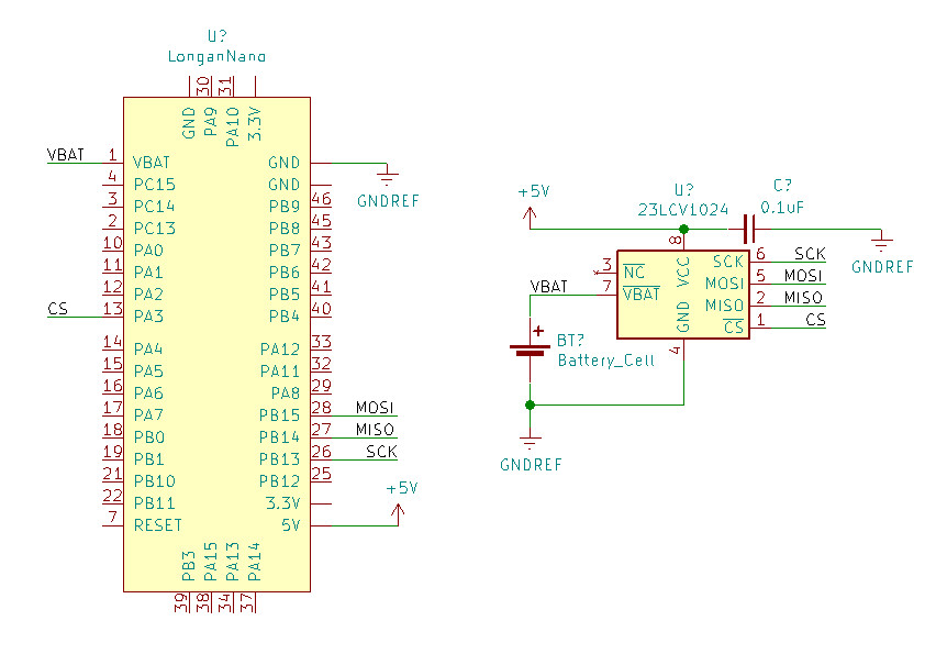
Hint: The VBAT pin can be optionally wired to an external battery (max 3.6V) to keep the SRAM contents intact if you disconnect power from the longan nano. This applies to the external SRAM and the longan nano's internal SRAM (through the VB pin). I wired both to a CR2032 battery, as shown in the schematic above, but you're free to skip that step.
It is assumed you'll be powering and flashing the longan nano from the USB-C port.
The driver
I found it easier to clone the longan-nano repo locally, and simply create a new example binary firmware.
First, you'll want to add the sram23x driver as a dependency in the Cargo.toml:
[dependencies]
sram23x = "0.2.1"
Next add the following code to examples/sram.rs. It's mostly a copy of examples/display.rs, with some minor changes which I'll explain later.
| #![no_std] | |
| #![no_main] | |
| use panic_halt as _; | |
| use embedded_graphics::fonts::{Font12x16, Text}; | |
| use embedded_graphics::pixelcolor::Rgb565; | |
| use embedded_graphics::prelude::*; | |
| use embedded_graphics::primitives::Rectangle; | |
| use embedded_graphics::{primitive_style, text_style}; | |
| use gd32vf103xx_hal::pac; | |
| use gd32vf103xx_hal::prelude::*; | |
| use longan_nano::{lcd, lcd_pins}; | |
| use riscv_rt::entry; | |
| use gd32vf103xx_hal::spi::{Spi, MODE_0}; | |
| use sram23x::*; | |
| #[entry] | |
| fn main() -> ! { | |
| let dp = pac::Peripherals::take().unwrap(); | |
| // Configure clocks | |
| let mut rcu = dp | |
| .RCU | |
| .configure() | |
| .ext_hf_clock(8.mhz()) | |
| .sysclk(108.mhz()) | |
| .freeze(); | |
| let mut afio = dp.AFIO.constrain(&mut rcu); | |
| let gpioa = dp.GPIOA.split(&mut rcu); | |
| let gpiob = dp.GPIOB.split(&mut rcu); | |
| let lcd_pins = lcd_pins!(gpioa, gpiob); | |
| let mut lcd = lcd::configure(dp.SPI0, lcd_pins, &mut afio, &mut rcu); | |
| let (width, height) = (lcd.size().width as i32, lcd.size().height as i32); | |
| // SRAM pins | |
| let sck = gpiob.pb13.into_alternate_push_pull(); | |
| let miso = gpiob.pb14.into_floating_input(); | |
| let mosi = gpiob.pb15.into_alternate_push_pull(); | |
| let spi1 = Spi::spi1(dp.SPI1, (sck, miso, mosi), MODE_0, 4.mhz(), &mut rcu); | |
| let hold = gpioa.pa0.into_push_pull_output(); | |
| let cs = gpioa.pa3.into_push_pull_output(); | |
| // Write abcdABCD to SRAM at memory address 0x00 | |
| let mut sram = Sram23x::new(spi1, cs, hold, device_type::M23xv1024).unwrap(); | |
| sram.set_mode(OperatingMode::Sequential as u8).unwrap(); | |
| let mut data: [u8; 8] = ['a' as u8, 'b' as u8, 'c' as u8, 'd' as u8, 65, 66, 67, 68]; | |
| sram.write_sequential(0x00_u32, &mut data).unwrap(); | |
| // Read from SRAM at memory address 0x00 | |
| sram.read_sequential(0x00_u32, &mut data).unwrap(); | |
| // Convert the last 4 bytes into an str, to be displayed on the LCD | |
| let sramstr = core::str::from_utf8(&data[4..]).unwrap(); | |
| // Clear screen | |
| Rectangle::new(Point::new(0, 0), Point::new(width - 1, height - 1)) | |
| .into_styled(primitive_style!(fill_color = Rgb565::BLACK)) | |
| .draw(&mut lcd) | |
| .unwrap(); | |
| let style = text_style!( | |
| font = Font12x16, | |
| text_color = Rgb565::YELLOW, | |
| background_color = Rgb565::BLACK | |
| ); | |
| // Create a text at position (20, 30) and draw it using style defined above | |
| Text::new(&sramstr, Point::new(5, 5)) | |
| .into_styled(style) | |
| .draw(&mut lcd) | |
| .unwrap(); | |
| loop {} | |
| } |
Get the full source code here.
The first change is to use a bigger font, and we'll include the sram23x crate and the spi module from the gd32vf103xx_hal crate:
| use embedded_graphics::fonts::{Font12x16, Text}; | |
| use gd32vf103xx_hal::spi::{Spi, MODE_0}; | |
| use sram23x::*; |
Next, we'll define what GPIO pins will communicate with the external SRAM. The sram23x crate is generic for various types of Microchip 23x memory devices, some which have a HOLD pin instead of VBAT pin. Even if a device does not have a HOLD pin, it must still be assigned when initating the device. That is purely due to my inexperience with Rust, and I welcome pull requests to help improve that ;)
| let sck = gpiob.pb13.into_alternate_push_pull(); | |
| let miso = gpiob.pb14.into_floating_input(); | |
| let mosi = gpiob.pb15.into_alternate_push_pull(); | |
| let spi1 = Spi::spi1(dp.SPI1, (sck, miso, mosi), MODE_0, 4.mhz(), &mut rcu); | |
| let hold = gpioa.pa0.into_push_pull_output(); | |
| let cs = gpioa.pa3.into_push_pull_output(); |
Here we're using PA0 for the hold pin, but it can be any other unused pin (ex: PE10). Either way, the sram23x crate won't use the hold pin if the device doesn't have one.
Next, we initiate the SRAM device and write the string of bytes abcdABCD to memory address 0x00.
| let mut sram = Sram23x::new(spi1, cs, hold, device_type::M23xv1024).unwrap(); | |
| sram.set_mode(OperatingMode::Sequential as u8).unwrap(); | |
| let mut data: [u8; 8] = ['a' as u8, 'b' as u8, 'c' as u8, 'd' as u8, 65, 66, 67, 68]; | |
| sram.write_sequential(0x00_u32, &mut data).unwrap(); |
Notice how we specified device type M23xv1024, that's just an internal name I chose for the 23LCV1024 device. Here's the full list of supported devices and their features:
| Device | Memory bytes | Memory bits | HOLD pin | Datasheet |
|---|---|---|---|---|
| M23x640 | 8 KB | 64 Kbit | yes | 23A640/23K640 |
| M23x256 | 32 KB | 256 Kbit | yes | 23A256/23K256 |
| M23x512 | 64 KB | 512 Kbit | yes | 23A512/23LC512 |
| M23x512 | 64 KB | 512 Kbit | no | 23LCV512 |
| M23x1024 | 128 KB | 1 Mbit | yes | 23A1024/23LC1024 |
| M23xv1024 | 128 KB | 1 Mbit | no | 23LCV1024 |
In this write operation, we're using sequential mode, which allows us to write any number of bytes "in sequence". There is also support for reading/writing in byte mode (1 byte at a time) and page mode (32 bytes at a time).
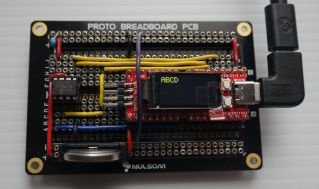
Finally, we read that sequence of 8 bytes from the SRAM, convert the last 4 bytes to an str slice, and display them on the LCD. If all worked well, you should see ABCD in yellow:
| sram.read_sequential(0x00_u32, &mut data).unwrap(); | |
| let sramstr = core::str::from_utf8(&data[4..]).unwrap(); | |
| let style = text_style!(font=Font12x16, text_color=Rgb565::YELLOW, background_color=Rgb565::BLACK); | |
| Text::new(&sramstr, Point::new(5, 5)) | |
| .into_styled(style) | |
| .draw(&mut lcd) | |
| .unwrap(); |
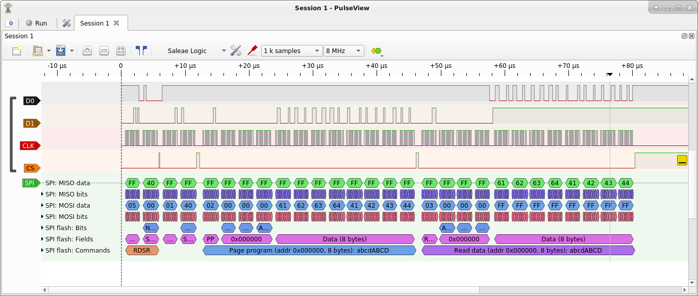
I connected an inexpensive Saleae clone 24MHz logic analyzer and checked the output using the open source Pulseview application, and here was the output:
Build the sram.rs firmware with cargo build --example sram --features=lcd --release, and then flash as usual.
That's all for now. Feel free to explore the docs as there are many more features I didn't discuss here.
https://blog.a1w.ca/p/rust-embedded-driver-microchip-23x-sram
2021-01-24 11:45:00 UTC